
Sound Blaster 1.0/1.5
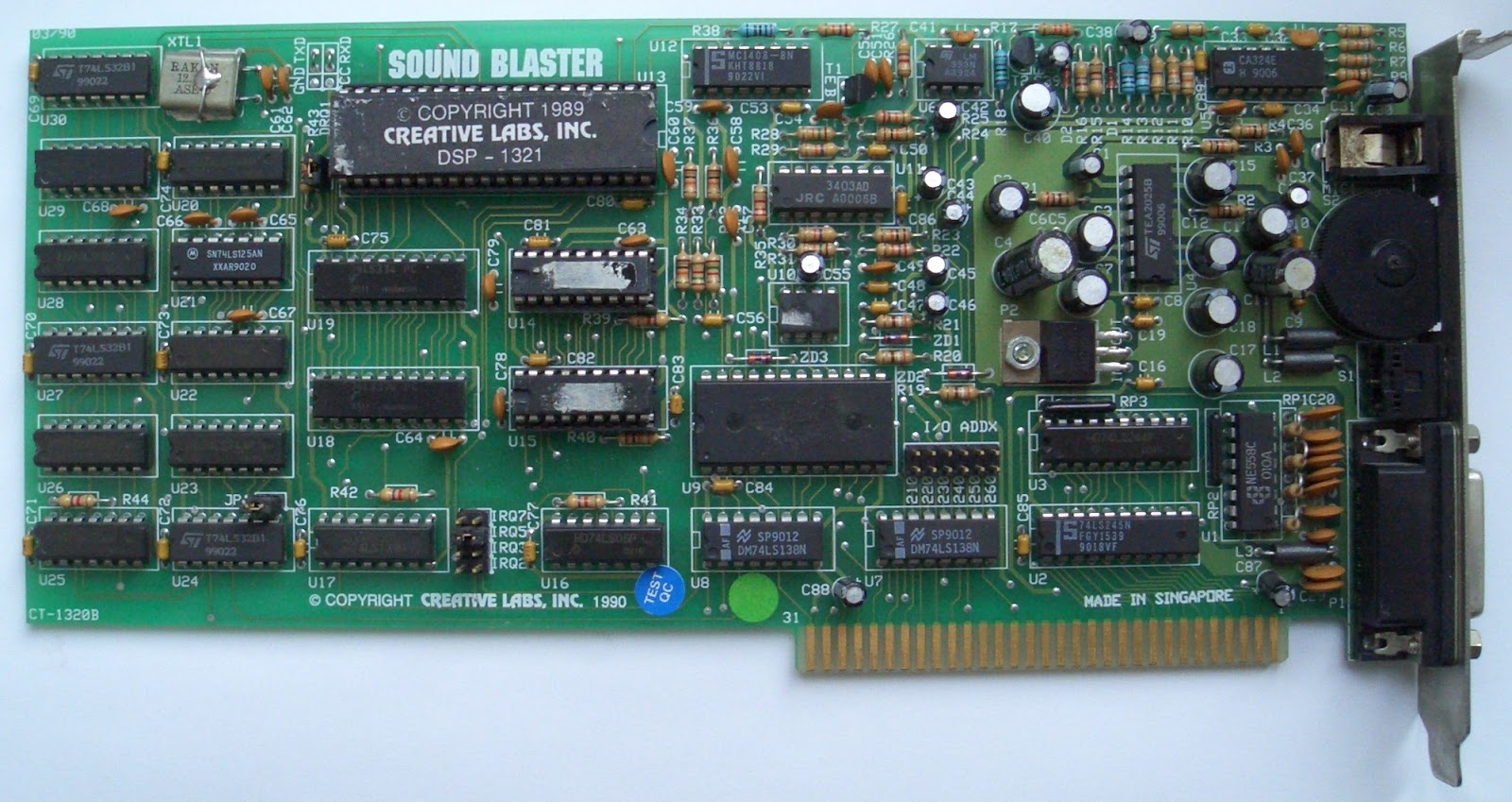
These are the original models of the Sound Blaster. The chief difference between the two is that the 1.0 version has two CMS-301 chips soldered onto the board while the 1.5 version has empty sockets for those chips. The CMS-301 chips are Creative's name (put on stickers) for Phillips SAA-1099 chips. These chips are the only source for stereo output on these cards, and if you can find two of these chips, you can turn a 1.5 into a 1.0. Adding the chips provides for a very good degree of compatibility with Creative Music Systems Card and Game Blaster software. This compatibility is not perfect because some programs and games (Taito) require the presence of a special chip found only on those cards.
These cards contain a single Yamaha OPL2 (YM3812 + YM3014) chipset. This chipset is the exact same chipset the Adlib Music Systems Card uses and is also located at the same I/O range (388/389h), which provides for perfect compatibility with any software supporting Adlib. These chips may be socketed or soldered.
The gameport on these cards can be disabled via removing JP1. It is IBM PC compatible and uses I/O address 201.
I/O addresses ranges include 210-21F; 220-22F; 230-23F; 240-24F; 250-25F; 260-26F.
Available IRQs are 2, 3, 4, 5, 7. The only DMA channel this card can use is 1 and it cannot be fully disabled, despite the DMACTRL jumper.
These cards have no on-board mixer, volume control is done by the application and the volume wheel at the back of the card. The output is amplified for headphones and unpowered speakers.
These cards support line out and mic in, there is no separate line in. The mic in jack is often rusty with these old cards.
The large socketed chip is the Digital Signal Processor (DSP). In earlier cards, DSP V1.05 is usually present. DSP V1.03 is also confirmed to exist. These DSPs will have a sticker label on them. Some later cards use a DSP V2.0. This DSP has an etched silkscreen on the chip. The DSP handles digitized audio and midi I/O. As the chip is socketed, it could be upgraded from a V1.xx to a V2.00. Doing so would allow the card to achieve compliance with MPC-1 standards.
DSP V1.xx supports single-cycle DMA mode, ADPCM modes from 8-4 bits, 8-3 bits and 8-2 bits. It supports 8-bit mono output up to 23,000 kHz or 11,000-13,000 kHz using ADPCM. It supports normal mode midi output. DSP V2.00 adds auto-initialize DMA mode and UART midi mode. The Sound Blaster is totally incompatible with the Roland MPU-401 midi interface, which is what early games that supported midi (generally the MT-32), used.
The gameport also supports midi input/output and can use gameport-to-midi cables.
This card uses T1 (Type 1) in the SET BLASTER line in your autoexec.bat. The default SET BLASTER variable is as follows:
SET BLASTER=A220 I7 D1 T1
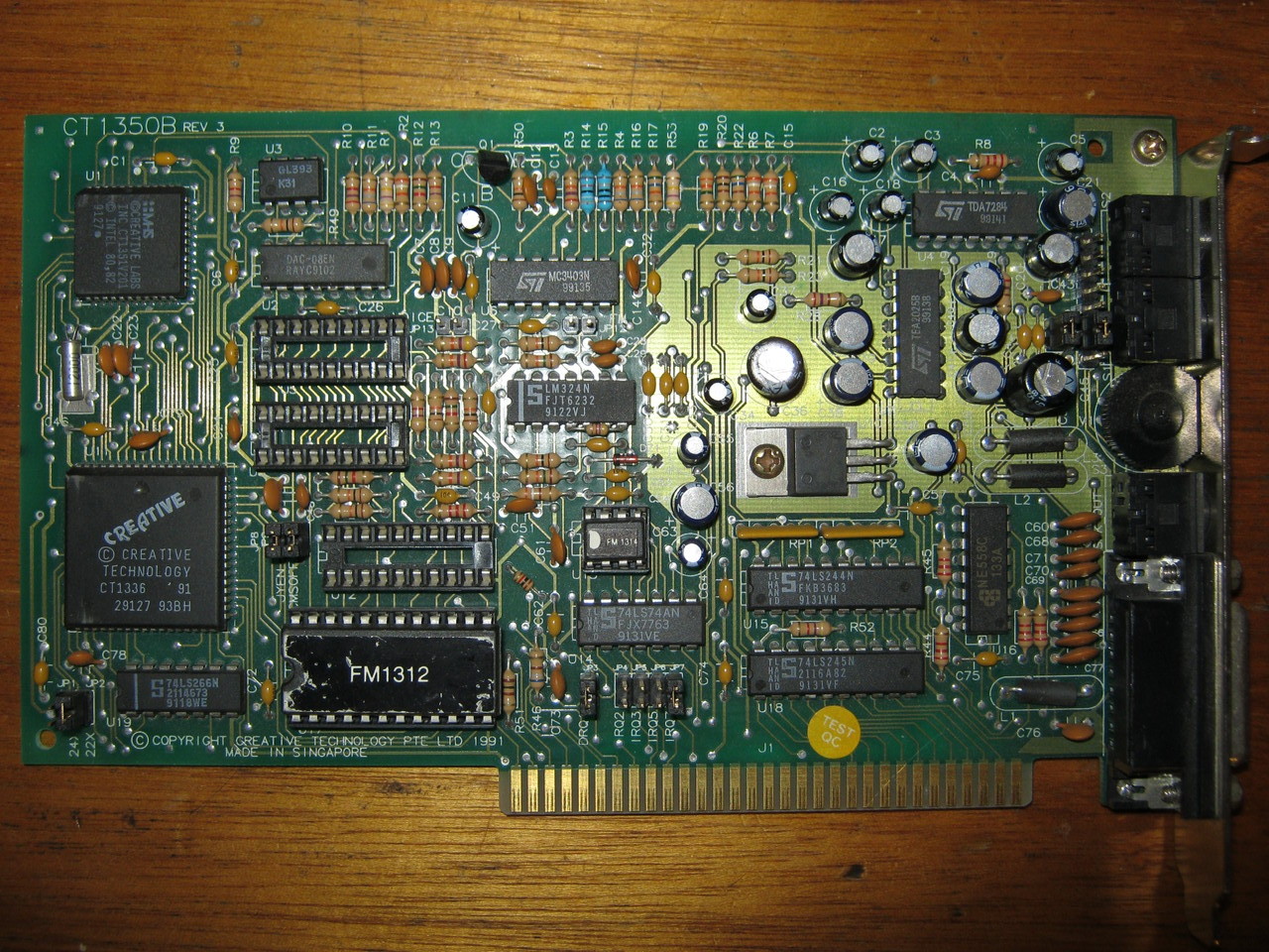
Sound Blaster Pro 1.0

These cards contain a dual Yamaha OPL2 (2 x YM3812 + 2 x YM3014) chipset. The chips may be socketed or soldered. This allows for stereo music output. Game Blaster compatibility was removed to achieve this.
This card supports a Panasonic CD-ROM interface. This interface is incompatible with standard IDE/ATAPI CD-ROM drives and requires special drives. The interface does not use any additional resources beyond the normal I/O address range this card uses.
I/O addresses ranges available are 220-233; 240-253.
Available IRQs are 2, 5, 7, 10. Available DMAs are 0, 1, 3. Using DMA 0 is not a good idea because games assumed DMA0 would be used for refreshing system RAM. However, AT class systems use dedicated refresh circuitry. Using IRQ 10 is also not a good idea, many games will not recognize IRQs higher than 7.
These cards support line out, line in and mic in.
This card uses DSP V3.01 and the CT-1345 mixer. DSP 3.xx adds support for stereo digital output up to 8-bit/22,050 kHz and mono digital output to 8-bit/44,100 kHz. It adds the high speed stereo and mono DMA modes. The CT-1345 supports output mixing in 8 volume steps in stereo for Voice, MIDI, CD and 4 volume steps in mono for the microphone. It has 8 volume steps for the Master Volume. It can also mix PC Speaker output in mono. It has a special register switch for digital stereo modes and a 3.2k output low-pass filter.
The volume control wheel is still present.
Has onboard CD-ROM input connector (white plug) and PC Speaker connector (2-pin).
Note that while this card has a 16-bit ISA slot connector, it is an 8-bit card. The 16-bit portion of the connector only allows the card to use IRQ 10 and DMA 0. It fits and works just fine in an XT machine.
This card uses T2 (Type 2) in the SET BLASTER line in your autoexec.bat. The default SET BLASTER variable is as follows:
SET BLASTER=A220 I7 D1 T2
Sound Blaster 2.0
Card uses DSP v2.01 or 2.02. It adds support for mono digital output to 8-bit/44,100 kHz. It adds the high speed mono DMA mode.
Card has two sockets for CMS-301 chips and a third socket for a specially programmed PAL16L8 chip which is required to interface with the CMS-301 chips. Without the PAL chip, which was included in the upgrade kit, the card cannot utilize the CMS-301 chips or provide any Game Blaster compatibility. The PAL has been decoded and GAL chips can be programmed to work in the socket. Boards have been shown to work with GALs manufactured by National Semiconductor and Lattice, but not with SGS Thompson GALs. Boards with a CT1336A chip do not work with the upgrade, even the official upgrade from Creative Labs.
Card has line out, line in and mic out and a volume wheel.
I/O addresses ranges include 220-22F; 240-24F.
This card uses T3 (Type 3) in the SET BLASTER line in your autoexec.bat. The default SET BLASTER variable is as follows:
SET BLASTER=A220 I7 D1 T3
Sound Blaster Pro 2.0

These cards contain a Yamaha OPL3 (YMF262 + YM512) chipset. The chips are always surface mounted. Stereo music output is not programmed in exactly the same way on the OPL3 as on the dual OPL2 of the Pro 1.0. Most games that support stereo OPL music support both types of Sound Blaster Pro. DragonSphere and Ultima Underworld are exceptions, the latter only supports the dual OPL2 of the Pro 1.0 and the former supports dual OPL2 much better than OPL3. DSP V3.02 has been seen on these cards, but V3.01 may be more common.
This card uses T4 (Type 4) in the SET BLASTER line in your autoexec.bat. The default SET BLASTER variable is as follows:
SET BLASTER=A220 I7 D1 T4
These are the first cards that have OEM versions that support a CD-ROM interface other than the standard Panasonic. The retail version, the CT-1600, has a Panasonic interface.
Sound Blaster MCV/Sound Blaster Pro MCV
CT-5320 & CT-5330

These are the Micro Channel versions of the Sound Blaster and Sound Blaster Pro, respectively for the IBM Personal System/2 computer series. They are full-length 16-bit Micro Channel cards.
The Sound Blaster MCV has identical features to the Sound Blaster 1.0/1.5 except they have no CMS-301 chips or sockets for them, no volume knob and cannot select IRQ2. I/O is selected in software.
The Sound Blaster Pro MCV has identical features to the Sound Blaster Pro 2.0 except it has no CD-ROM interface, no volume knob and cannot select IRQ2. I/O, IRQ and DMA are all selected in software.
These cards may not work properly in high speed Micro Channel systems. Like all Micro Channel cards they require .ADF files to configure the cards (partially) when inserted into a Micro Channel system. Compatibility wise they may be a bit more finicky than ISA sound blasters.
The Sound Blaster MCV should use T1 in the SET BLASTER line in your autoexec.bat. The default SET BLASTER variable is as follows:
SET BLASTER=A220 I7 D1 T1
The Sound Blaster Pro MCV should use T5 in the SET BLASTER line in your autoexec.bat. The default SET BLASTER variable is as follows:
SET BLASTER=A220 I7 D1 T5
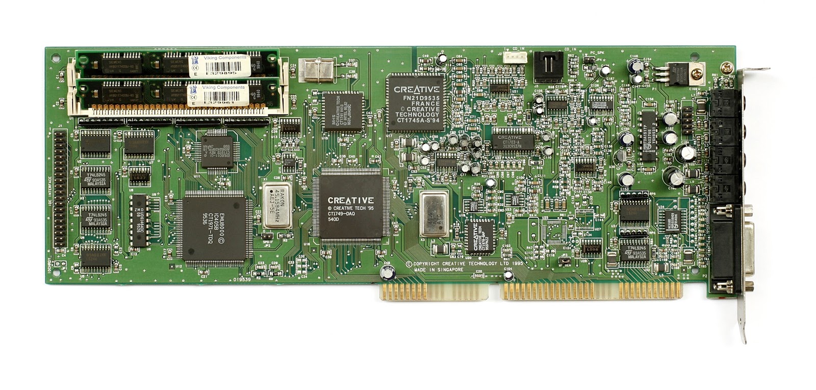
Sound Blaster 16
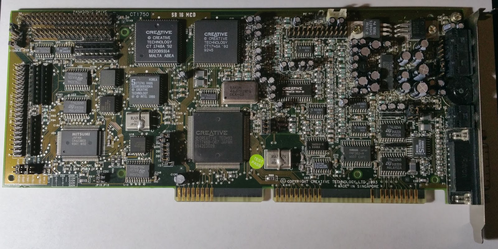
Early cards contain a Yamaha OPL3 (YMF262 + YM512) chipset. Later cards may have true OPL3 functionality included in the CT-1747 chip. Even later cards may use the CT-1978 CQM chip, which approximates OPL FM Synthesis (or improves upon it according to Creative.) CQM in my opinion has a harsher sound than Yamaha FM Synthesis.
Card has line out, line in and mic out.
Has onboard CD-ROM input connector (white plug and/or black plug) and PC Speaker connector (2-pin). Later cards may have AUX or MODEM or TAD connectors.
Many boards have a 26-pin header for a Waveblaster-compatible midi daughtercard.
Early cards still have a volume wheel; these cards also have jumpers that allows the user to disable the on-board amplifiers, making the wheel useless.
Boards frequently support the Panasonic, Sony and/or Mitsumi CD-ROM interfaces or an IDE/ATAPI interface. The Panasonic interface does not take up extra resources, but the Sony, Mitsumi and IDE interfaces require an IRQ and I/O for the IDE. They may or may not be able to be disabled.
Many of these cards have an empty socket for a CT-1748 Advanced Signal Processor (ASP) or Creative Signal Processor (CSP). Some cards have the chip soldered onto the board. This processor, which was supposed to provide surround sound and more, is not known to be used in games other than TFX. There are jumpers to enable or disable the chip if the chip is in a socket.
This card uses DSP (maybe V4.01) V4.04, V4.05, V4.11, V4.12 and V4.13 and the CT-1745 mixer. DSP 4.xx adds support for mono or stereo digital output up to 8-bit/44,100 kHz or 16-bit/44,100 kHz . It scraps the high speed modes of the Pros but allows the other pre-existing single-cycle and auto-init DMA modes to support digitized sound up to 44,100 kHz in 8-bit or 16-bit. If a game uses single-cycle DMA modes, the listener will experience pops and cracks that would not be present in earlier cards. DSPs 4.05 and lower are very noisy when it comes to digital audio output.
A UART mode compatible MPU-401 midi interface is added at I/O 330 or 300. This interface may also be disabled on some cards via jumper. It will not work with games requiring a 100% compatible Roland MPU-401 interface (namely games requiring normal/intelligent midi mode support). Such games are typically Roland MT-32/LAPC-I games; General MIDI games will almost invariably work with a UART compatible MPU-401 midi interface. The UART MPU-401 interface will communicate through the gameport or the wavetable header. DSPs 4.11-4.13 are subject to the hanging or incorrect notes midi bug, with some cards more affected than others. The bug tends to rear its head when the DSP is also trying to process digitized sound at the same time as midi.
I/O addresses ranges include 220-233; 240-253; 260-273; 280-293. Available IRQs are 2, 5, 7, 10. Available low/8-bit DMAs are 0, 1, 3. Available high/16-bit DMAs are 5, 6, 7.
In the early cards, there are jumpers to select I/O addresses, IRQs, DMAs, Midi I/O. Later cards allow software IRQ and DMA selection through the Creative Configuration Manager. This program must be loaded on bootup to assign resources to these cards. Even later cards are Plug-n-Play compatible, eliminating jumpers for I/O and many other settings.
The CT-1745 mixer supports output mixing in 32 volume steps in stereo for Voice, MIDI, CD, Line-In, 32 volume steps in mono Microphone and 4 volume steps in mono for the PC Speaker. It has a 32 volume step Master control. It allows 4 levels of Gain control and 16 levels of Treble and Bass control. It does not have the stereo switch of the CT-1345 and uses dynamic filtering instead of a set low-pass filter. Certain cards may not include the CT-1745 mixer chip, their mixers tend to lose the Treble and Bass control and sometimes the Gain control. These cards use chips marked ViBRA. It is unknown whether any games use the Treble and Bass controls.
The last cards in the series were the Sound Blaster 16 WavEffect cards. CT-4170 is an example of such a card. These use 2 low DMAs instead of 1 low DMA and 1 high DMA for 16-bit sound. This may be incompatible with games that expect to use a high DMA for 16-bit digitized sound. Few use the H-DMA channel.
This card and its ISA successors all use T6 (Type 6) in the SET BLASTER line in your autoexec.bat. The default SET BLASTER variable is as follows:
SET BLASTER=A220 I5 D1 H5 P330 T6
H refers to the high DMA channel, P refers to the MPU-401 midi I/O used. By this time, the default IRQ has changed to 5, probably to avoid conflicts with the printer IRQ.
Sound Blaster AWE32/32
See Sound Blaster 16, above for basic capabilities. Changes include:
The biggest change is the inclusion of the E-mu (EMU8000 and EMU8011) midi processor chipset. Except as noted below, this chipset can use 1MB of ROM plus up to 28MB or RAM to store sampled instruments contained in files called SoundFonts. Two 30-pin SIMM slots are provided, but they use plastic retention clips that are very cheap and easy to break. (Epoxy is your friend if they do.) Up to 16MB SIMMs can be used, although 28MB is the maximum that the E-mu chipset can address. While some DOS games supported these cards, they typically only used the ROM samples.
Sound Blaster 32 and Sound Blaster AWE32 Value cards generally do not have a wavetable header. Value cards also do not have SIMM slots for RAM upgrades. Sound Blaster 32s do not have RAM onboard and use ViBRA chips but do have SIMM slots. AWE32s usually have the ASP/CSP chip of the 16s soldered in.
The AWE32 and AWE32 Value come with 512K of RAM for Soundfonts. When RAM is inserted into the slots, the on-board RAM is disabled. There is a "Goldfinch" card that can be used to upgrade a Sound Blaster 16 with the EMU capabilities. Most Goldfinch cards do not have an audio-out mini-jack, seeing as they were an OEM product, so a special cable will be needed to output sound.
Many of these cards have a 2-pin header for an S/PDIF connector. This S/PDIF can only pass EMU and OPL sound output.
Typical cards have a line in, mic in, line out and speaker out jacks. Earlier cards come with Panasonic, Sony and Mitsumi CD-ROM interfaces, later cards use IDE. If the IDE interface on these cards cannot be disabled or changed to an unused portion of the I/O space, then you may have a resource conflict with your motherboard.
The default SET BLASTER variable is as follows:
SET BLASTER=A220 I5 D1 H5 P330 T6 E620
The E variable refers to the starting I/O address of the EMU8000. Its address depends on the addresses at 220-280. If the main I/O starts at 220, then 620-623, A20-A23, E20-E23 are used. If I/O starts at 240, then 640, A40, E40 are used. I/O address 100 is used for the Creative 3D Stereo Enhancement effect of dubious value.
In the AWE32 series, the cards choose IRQ and DMA in software, writing the settings to a small EEPROM. The user still needs to set the I/O addresses manually for some of the earlier cards. Later cards only tend to allow you to disable the MPU-401 interface and enable the SIMMs by jumper. Even later 32s support ISA PnP for configuration, but those are virtually indistinguishable from the AWE64s.
There is no difficulty with trying to access a midi device connected to the wavetable header or gameport. If you are trying to access the EMU as a midi device, and the program does not specifically support the AWE32, then you will have to load a TSR utility called AWEUTIL in order for the EMU to emulate a full midi device. AWEUTIL takes up alot of conventional memory and is incompatible with programs that use DOS extenders (DOS4GW, CWSDPMI, DOS32A) such as DOOM and most DOS games released in 1994-present. It also requires a system with a working Non-Maskable Interrupt (NMI).
Since AWE32s use DSPs 4.11-4.13, they will suffer from the DSP hanging note bug described above when using ordinary midi devices. The ones without a CT-1747 chip will use the CQM method of FM emulation (see Sound Blaster 16, above). This includes most of the AWE32 PnPs and SB32s. There is also the occasional card with YMF-262 or YMF-289 ICs, which are genuine Yamaha FM OPL3 chips. For these cards, you cannot get S/PDIF FM audio output.
Sound Blaster AWE64

To DOS, this card is identical to the AWE32. In Windows, it can provide 32 more software voices of polyphony in midi by use of the Wayesynth software. This uses sythesized sounds, not digitized sounds from a soundfont file, and was little supported.
Sound Blaster AWE64 Gold cards have S/PDIF connectors which add digitized sound support as well as OPL and EMU. They come with 4MB of Soundfont RAM, whereas the standard card comes with 1MB and the value card 512KB. The Gold cards come with gold-plated RCA jacks, the other cards must make do with mini-jacks.
All AWE64s use CQM, but as they use DSP 4.16, they no longer suffer from the DSP hanging note bug. All use CQM for FM synthesis emulation.
To upgrade the RAM to the 28MB maximum, one has to find proprietary Creative memory modules or use an adapter like AWE-SIMM or SIMMCONN with 30-pin SIMMs.
Thanks to wikipedia for providing fair use images.